Table of contents
Installing Your Poly Tank

- Correct rainwater tank installation is critical to the effectiveness and longevity of your tank. If this guide is not followed then Bushmans guarantee may be voided.
- You can view the PDF version of our brochure and installation guide here.
- Bushmans services QLD, VIC, NSW, ACT, SA & NT, including Sydney, Melbourne, Brisbane, Adelaide and all surrounding areas. Please contact us to enquire about delivery in your area.
How to Videos
Tank Installation Steps
Above Ground:
Steps 1-3 on pad
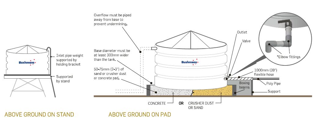
- Prepare a reinforced concrete pad that is level and 300mm wider than the diameter of the tank OR prepare an earth ring 300mm wider than the diameter of the tank so that no part of the tank is bearing on the wall. Fill is to be consolidated fill with 50-75mm (2-3”) of sand or crusher dust on the surface.
- Roll the tank into position (Note: If positioning requires a crane, this will be at the purchaser’s expense).
- Secure the tank or fill it with 85mm of water to prevent blow-away (Note: No responsibility is taken for tanks being damaged in this manner).
- Water Inlet: Direct water into the tank through the strainer. Fixed inlets must be supported and have a flexible hose fitted (similar to outlet instructions). The inlet pipe must be supported by the stand.
- Water Outlet: Connect your outlet using a flexible hose 1000mm (39”). The hose must be placed between the valve and any other plumbing or rigid pipe work. Elbow fittings must be used as shown.
- Water Overflow: Connect the overflow. Water must be piped away from the tank. Important: water capacity of the inlet must equal the water capacity of the overflow. For example, two 100mm (4”) inlets = same capacity overflow).
Steps 1-3 on stand
- Prepare a stand with hardwood decking, ensuring gaps are no greater than 25mm (1”). The decking must be structurally supported by bearers strong enough to prevent sagging when the tank is full. Ensure the stand is engineered to hold the weight of the product at full capacity.
- Lift the tank into place using a crane (Note: If positioning requires a crane, this will be at the purchaser’s expense).
- Secure the tank or fill it with 25mm of water to prevent blow-away (Note: No responsibility is taken for tanks being damaged in this manner).
- Water Inlet: Direct water into the tank through the strainer. Fixed inlets must be supported and have a flexible hose fitted (similar to outlet instructions). The inlet pipe must be supported by the stand.
- Water Outlet: Connect your outlet using a flexible hose 1000mm (39”). The hose must be placed between the valve and any other plumbing or rigid pipe work. Elbow fittings must be used as shown.
- Water Overflow: Connect the overflow. Water must be piped away from the tank. Important: water capacity of the inlet must equal the water capacity of the overflow. For example, two 100mm (4”) inlets = same capacity overflow).

In Ground:
- Before commencing, check for underground pipes and ensure excavation work does not infringe on the weight bearing capacity of adjacent structures. Excavate the hole in depth to allow for 50-75mm of bedding material and a maximum depth of 1/3 of the tank wall height. Excavate the hole in diameter to allow for a 150-200mm gap between the tank wall and the surrounding soil (the site is not suitable if there is water or if the floor of the hole is unstable). Spread washed river sand into the hole and compact it with a
plate compactor, to provide a firm level base. Check that no rocks, roots or sharp objects penetrate the sand base. - Tank must be lowered into the hole squarely by crane (if positioning requires a crane this will be at purchaser’s expense).
- Prior to starting to backfill, the tank must be filled with water to a level marginally above ground height. The soil taken from the hole must not be used as the backfill under any circumstances. Spread a 200-300mm layer of sand around the base of the
tank. Manually compact the sand ensuring that all the voids are filled. Continue adding sand in 200-300mm layers, ensuring each time that it is well compacted into all areas until it comes to within 150mm of the surface. Restore remaining 150mm with fresh soil. - Water Inlet – Water should be directed into tank through the strainer. Fixed inlets must be supported and have flexible hose fitted (similar to outlet instructions). Inlet pipe must be supported by stand.
- Water Outlet – Connect your outlet with flexible hose 300mm (12”) in length. The hose must be placed between the valve and all other plumbing or rigid pipe work. Elbow fittings must be used as shown.
- Water Overflow– Overflow – Connect overflow. Water must be piped away from the tank. Important: Water capacity of the inlet must equal water capacity of the overflow e.g. 2 x 100mm (4”) inlets = same capacity overflow.


Standard Delivery:
- Make sure tank pad is level and position tank.
- Mark outlet position on tank.
- Drill outlet hole to suit tap or gate valve fitting with wither a 22mm spade bit, or a 46mm (1 inch outlet) or 63mm (2 inch outlet) hole saw.
- Next use a 98mm hole saw to drill out overflow as per Overflow Installation leaflet in the kit. The overflow must be positioned in the middle of the flat spot.
- Insert overflow elbow into drilled hole until seal touches tank wall and screw into place using supplied screws. Push ‘mozzie’ screen or overflow strainer into overflow outlet hole until it bottoms out.
- Remove strainer screws and remove strainer.
- Place conduit in strainer hole, feed it through drilled outlet hole.
- To insert fitting in outlet, undo nut off outlet and slide outlet and washer down conduit. Pull through from outside.
- Screw nut on and tighten firmly by hand (left handed thread).
- Place thread tape onto outlet thread and fit ball valve. Tighten with multigrips.
- Place strainer back into tank and screw back in to place so it is sealed and vermin proof.
- Assemble flex hose using thread tape, attach elbow to ball valve.
Bushmans Checklist
On-site delivery
- Check you’re prepared for our Customer Care team member to unload tank, drill outlets, fit taps & seal.
- Check there is suitable and safe site access (see preparing for delivery).
- Site must be prepared as per instructions.
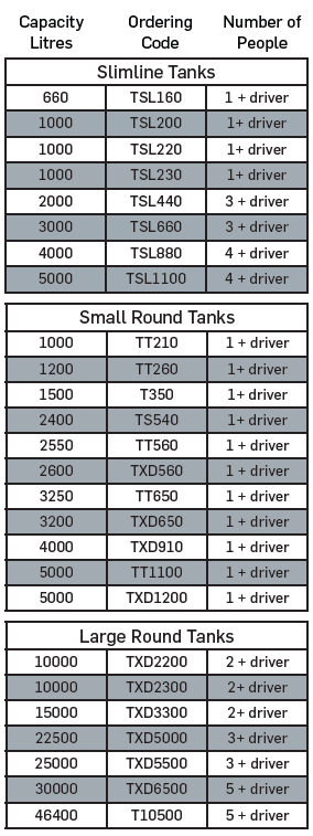
- Check enough people are present to assist tank positioning (see table ‘assistance required’ below).
- Water is immediately available to put 85mm in tank to prevent blow-away.
Fittings Installation
- Check there is suitable and safe site access (see preparing for Delivery)
- Check enough people are present to assist tank positioning (see table ‘assistance required’ below).
- Water is immediately available to put 25mm in tank to prevent blow-away.
Outlet Position
- All low outlets should be centre of rib or as low as 115mm from ground level. Note: T10500 model, the centre of the outlet should be 115mm from ground level.
Tools required
- Fitting and site preparation: Suitable ladder, drill, 6m length rope, deburring tool, multi grips, electrical conduit (12mm), thread tape (plumbers tape), tape measure & marker.
- Hole saws and arbour – Brass Outlets: 46mm hole saw for 1”outlet, 63mm for 2” outlet, 95mm for 3″ outlet
- Hole saws and arbour – Poly Outlets: 57mm hole saw for 25mm outlet, 60mm hole saw for 40mm outlet, 76mm hole saw for 50mm outlet, 118mm hole saw for 80mm outlet
- Overflow: 95mm for 90mm overflow and 121mm for 100mm overflow
- Slimline Tanks: 25mm spade bit to drill into the 1”pre-moulded outlet.
- Phillips screwdriver bit (our driver is trained to install tank fittings and carries the tools required for fitting).
Preparing for Delivery
This Easy Step Installation Guide will help you prepare for the arrival of your new Bushmans Tank.
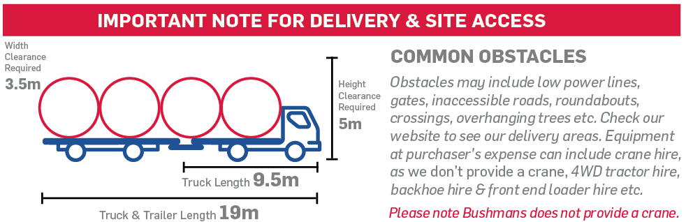
Delivery & Safe Access
- To deliver your tank without damage, please notify Bushmans Customer Care (driver) prior to delivery if there is not sufficient space for an oversize semi-trailer to turn around, or if there are any obstacles the driver should be aware of. A driver will conduct a pre-delivery site assessment and will require that an exclusion zone is set up on the side of the truck where the tank is to be unloaded.
- Please note: Safety is our top priority. If the site does not meet safety requirements for unloading, our driver will choose an alternative safe location. Customers must provide able-bodied assistance for unloading, if not, any additional costs for equipment or services will be at the purchaser’s expense. If the tank is moved by the customer after delivery, fittings will not be installed, and the customer assumes full responsibility for relocation and installation.
- Note: Due to WHS drivers will not unload or transport the tank to the installation-site, or leave the tank on-site if insufficient assistance or unsafe access is provided. The driver has the final decision to assess suitability of the site. Bushmans take no responsibility for tanks being damaged if site is unprepared. If delivery cannot be made to your site Bushmans will automatically attempt delivery again at the purchaser’s expense.

Delivery Onsite
- This is where our driver will help sit the tank only if the provided conditions are met as per Checklist, if you have followed the guidelines, the site is prepared and safe, our driver will install your tank. Note: Due to WHS drivers will not unload or transport the tank to the installation-site, or leave the tank on-site if insufficient assistance or unsafe access is provided. The driver has the final decision to assess suitability of the site. Bushmans take no responsibility for tanks being damaged if site is unprepared. If delivery cannot be made to your site Bushmans will automatically attempt delivery again at the
purchaser’s expense.
Fittings Installation Method
- Bushmans fittings are installed at the time of delivery. If the site is unprepared or the customer declines to have the fittings installed during delivery, the responsibility for installation will fall to the customer. Our delivery team cannot return to install fittings at a later date.
Plumbing Fittings
- Please advise prior to delivery if you need any extra Bushmans fittings or valves. Extra fittings are available upon request at additional cost. Check with local council for regulations relating to rain water tank installations. See fittings & accessories for more information. When plumbing the inlet, overflow or outlets, ensure allowances are made for the poly tank to move position, expand and contract. Typical PVC or metal fittings are relatively rigid and inflexible.
Note: Purchase and delivery of any additional plumbing fittings and pipes are responsibility of purchaser. Our guarantee specifies a 1000mm flexible hose be fitted to the outlet.
Securing your tank
- When your tank arrives you must put at least 85mm (3.3”) of water into the tank, if water is not available ensure that the tank is tied down to secure it from blow-away and damage. Water tank stands can be used but must be designed by a qualified consulting engineer. Note: Bushmans take no responsibility for tanks being damaged if the tank is not secured properly. Due to WHS our drivers and service people are not permitted to work at heights and therefore cannot assist in placing or servicing tanks on stands.
- These are the extra number of people required on-site at the time of delivery to assist in positioning the tank. It is recommended to use lifting devices or heavy machinery (tractor with forks – Franna or Loader) if available.

Bushmans Guarantee
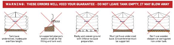
- If the steps in this guide are not followed, Bushmans guarantee is null and void.
- Please note: Your tank cannot be unloaded without required assistance (the table above outlines the extra number of people required onsite at the time of delivery to assist in positioning the tank). Do not work alone or enter the tank as this is a confined space. Always wear safety gear and safety eye glasses when drilling. Do not lift the tank with water inside. Remember, your tank must be installed correctly to ensure long life, and so you do not void your guarantee.

Industrial Tank Installation
The correct installation of an industrial tank is critical to the life and serviceability of the product.
The guidelines below will help ensure the tank is installed correctly.
- Tank Foundation: Place tank on a clean, smooth, and properly designed concrete foundation. Ensure NO rubbish or debris of any kind is trapped between the tank and its foundation or support. Make foundation 0.5M larger in diameter than the diameter of the tank.
- For additional information refer to our guide Installation of the Tank at Site
- AS/NZS4766 : 2006 Chemical Tank Standard: All vertical, above ground tanks are designed and manufactured using polyethylene raw material in accordance with AS/NZS4766
- Liquid capacity markers: Approximate indicators are not intended for precise measuring or metering. Fill vertical tanks only to top of sidewall.
- Nominal / Working Capacity: Calculated vertical tank capacity is to top of the sidewall.
- Polyethylene tanks expand and contract which will affect volume. The degree in which this occurs depends on the size of the tanks, wall thickness, specific gravity (or relative density) of contents, temperature of contents and ambient temperatures.
- Fittings: Support hoses, piping and valves independent of tank sidewall and roof. Flexible connections must be used to protect your tank guarantee!
- Shield all fittings, valves, and piping from physical impact and to protect personnel from chemical spray or release.
- Installation: Hydro test (water test) tank system for 24 hours before introduction of chemical to confirm there is no damage to fittings caused during transport or installation. If necessary, remove all test water to prevent reaction with chemical stored.
- It is the installer’s responsibility to follow all appropriate State and/or National safety precautions. Bushmans have provided the following information as guidelines for tank use and installation. It does not address safety issues which may be present at specific tank installation sites. Use appropriate safety practices when handling any tank and/or using heavy equipment.
- Upon delivery, inspect your tank immediately for defects or shipping damage. Any discrepancies, or product problems, should be noted on the Customer Care team member’s delivery receipt book.
- When unloading your tank from the delivery truck, avoid its contact with sharp objects. Forklift blades can cause significant damage if proper precautions are not taken.
- Do not allow tanks to be rolled over on the fittings.
- Large storage tanks, whenever possible, should be removed from truck bed by use of a crane or other suitable lifting device. (Lifting device is at purchasers expense)
- Keep unloading area free of rocks, sharp objects, and other materials that could damage the tank.
- If tank is unloaded on it’s side, carefully brace to prevent rolling so external fittings are not damaged.
- Polyethylene tanks are HEAVY. Use adequate equipment and properly trained personnel to off load and place tanks in final position.
- Do not stand or work on top of tank. The tank surfaces are flexible and slippery and a dangerous fall could occur. Remember – Safety First
- Tanks are confined spaces. Follow proper entry procedures. Establish an adequate retrieval plan.
- Incorporate chemical manufacture’s “best practices” for product being stored.
- Confirm compatibility of tank, fittings, and gaskets for chemical to be stored before permanent installation. If necessary, test the tank, fitting, and gasket materials of construction for compatibility with the specific chemical application.
- Place valves as close to the tank as possible, and be sure valves can be easily accessed.
- Install flexible connections to allow tank to expand and contract and for protection from pump vibration. Adequately support valves, piping, and hoses. Refer Bushmans guide on Flexible Connections.
- Install guards, shields, barriers, and walkways to protect tank, fittings, and piping from damage by impact and to protect personnel from chemical release.
- Vent tanks to prevent pressure or vacuum.
- Label tank with the appropriate warning label for the particular chemical to be stored. Do not remove Bushmans general warning labels. Replace damaged or illegible labels immediately.
- We recommend that you hydro test the tank for at least 24 hours prior to loading with chemical.
- Hold Down Lugs are designed to hold tanks in central position. Bolts must allow tank diameter to expand and contract, so it is important to position bolts in center of slotted hole in lug. Ensure bolts do not apply downward pressure on the lug. Bushmans Hold Down Lugs are not designed for wind or seismic restraint capabilities.
- Support the bottom of tank firmly and completely. Concrete pads provide the best foundation, and are recommended for industrial tanks. Prepare a reinforced concrete pad that is level and at least 0.5M greater than the diameter of tank.
- In the event you deem that the base loading bearing factors are not important, prepare a ring on the ground at least 0.5M greater than the diameter of the tank so that no part of the tank is bearing on the ring edge. Fill is to be consolidated with 50–75 mm of sand or crusher dust on top surface. You must maintain the consolidated fill in good condition during the service life of the tank. (If positioning requires a crane, this must be at purchaser’s expense)
- Steel support stands concentrate the loaded tank weight onto the stand leg pads. It is recommended that stands be mounted on a concrete base. Bolting of stands is necessary to prevent movement due to agitation, wind, seismic loads and accidental contact. It is the purchasers responsibility to ensure that support structure is designed adequately for the purpose.
- Failure to comply with handling and installation instructions will void all guarantees.
- For guidance on tank maintenance refer Bushmans Annual Chemical Tank Inspection Checklist
WARNING: Failure to provide proper foundation support constitutes a misuse of the tank and will void your guarantee!
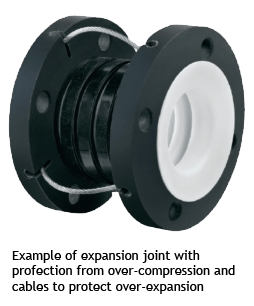
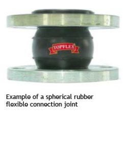
Flexible Connections
The number one reason for tank failures is due to improper installation. It is important that you design and install your pipe work using good installation practices. This is your responsibility. Flexible connections are required on fittings installed on the lower 1/3 of the tank sidewall to allow the tank to expand and contract and to protect the tank from pump vibrations. Good installation practices will include the provision of adequate support for pipe work, or additional fittings that may impose any stress on the tank.
1. Install flexible connection in accordance with the specific manufacturer’s installation guidelines. These guidelines may include:
- The “breech opening” in the piping for the flexible connection should be within 3mm of the relaxed length of the flexible connection.
- Flexible connections are not to be used for correcting piping misalignment. The flexible connection and mating flanges must be installed in a centered and neutral position.
- Attach only FULL FACE flanges to the flexible connection. They are not designed to attach directly to tank wall.
- Ensure adequate clearance between bolt ends for full use of flexible connections.
- Torque to 27 joules (20 ft. lbs) using crisscross tightening pattern.
- Provide pipe support adjacent to the flexible connection.
Flexible Connection Recommended Minimum Specifications:
- Axial Compression = 38mm
- Axial Extension = 15mm
- Lateral Deflection = 19mm
- Angular Deflection = 14°


- Use thread sealant for pipe thread preparation.
- Support hose adequately but do not restrict its ability to move in horizontal directions.
It is the responsibility of the tank purchaser to install the appropriate flexible connections, bolts and gaskets between the tank and the plumbing. This is important as the Bushmans 5 year Industrial tank guarantee is only valid if the installation has appropriate flexible connections.
The use of rigid piping or the failure to provide for the expansion of the tank will void all guarantees.


Aqualine Installation
Download our Aqualine Brochure and Installation guide
How to Videos
Prep & Completion Requirements
Aqualine tanks are designed for installation on a flat level surface that is able to withstand the weight of a full water tank. To do this the site must be prepared correctly. The correct preparation of your site will ensure that the tank will be trouble free for many years. There are three types of bases for Aqualine Tanks, these being free draining sand, a crusher dust base or a concrete pad base.
NB: If the pad is not prepared properly and the install team arrive and have to wait or come back, the customer will be responsible for any expenses including but not limited to travel, accommodation and wages incurred by Aqualine.
Concrete Base
The concrete slab must be designed to carry the weight of the tank filled with water. Aqualine can provide specific
slab diagrams for basic installations. For more complex installations an engineer may be required.
Sand Or Crusher Dust Base
- Preparing the Sand or Crusher Dust Pad:
- The sand or crusher dust pad must have a diameter which is more than 2 metres wider than the tank diameter.
- The preferred base material should be free draining and must be free of any sharp objects, clay lumps, stones or material such as roots.
- If crusher dust is used it must have particle sizes of less than 5mm and the tank base must have a Geotextile covering to protect the liner.
- The pad must be stable prior to construction
- The fill must be a minimum depth of 150mm and compacted to a minimum capacity of 50kPa.
- It is important that the pad is 100% level.
- For a tank base cut into a sloping site, make sure there is
adequate drainage to direct water away from the pad. - A retaining wall may be required on sloping sites.
NB: The cubic metres of base material is for a flat site with a minimum of 150mm. Base preparation guidelines are designed for stable soils. Customers should consult their engineer on specific base and slab specifications. Tanks located in cyclonic regions will require a concrete ring beam.
Base Preperation Material Required
| Tank Code | Base Material |
| ASL20 | 3.85mᶟ |
| ASL30 | 5.16mᶟ |
| ASL45 | 6.66mᶟ |
| ASL60 | 8.36mᶟ |
| ASL80 | 10.25mᶟ |
| ASL100 | 12.33mᶟ |
| ASL125 | 14.60mᶟ |
| ASL150 | 17.07mᶟ |
| ASL180 | 19.73mᶟ |
| ASL210 | 22.58mᶟ |
| ASL245 | 25.63mᶟ |
| ASL280 | 28.86mᶟ |
| ASL320 | 32.29mᶟ |
| ASL360 | 35.91mᶟ |
Day Of Installation
- If the fitting and strainer locations have not been specified, then someone will need to be on-site to instruct the installers on the required locations, this must be finalised prior to truss installation.
- Once the installation has been completed the tank must have 300mm of water supplied by the customer to secure and set the liner. This must happen on the day of installation. If water is not added on the day this can void the warranty.
- A 75mm high by 400mm wide layer of blue metal or aggregate must be placed around the circumference of the tank to prevent erosion when water runs off the roof. If no blue metal or aggregate is placed the warranty will be voided.
- Inspection hatches should be locked to prevent unauthorised entry (customer to provide lock).


