Water Tank Installation and Delivery
Installing Your Tank
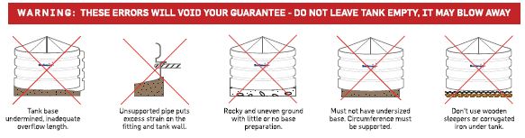
Correct rainwater tank installation is critical to the effectiveness and longevity of your tank. If this guide is not followed then Bushmans guarantee may be voided.
You can view the PDF version of our brochure and installation guide here.
Bushmans services QLD, VIC, NSW, ACT, SA & NT, including Sydney, Melbourne, Brisbane, Adelaide and all surrounding areas. Please contact us to enquire about delivery in your area.
How to Videos
- Video on How to Prepare the base and site for tank Installation
- Video on How to Prepare For Your Bushmans Tank Delivery
- Video on How to Manage the Final Steps in the Installation of Your New Poly Water Tank
Tank Installation Steps
Above Ground:
Steps 1-3 on pad
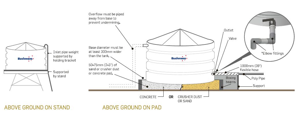
- Prepare a reinforced concrete pad that is level and 300 mm wider than the diameter of tank OR prepare an earth ring 300mm wider than the diameter of the tank so that no part of the tank is bearing on the wall. Fill is to be consolidated fill with 50-75mm (2-3”) of sand or crusher dust on surface.
- Tank is rolled to position (if positioning requires a crane this will be at purchaser’s expense).
- Tank must be secured or water filled to 25mm to prevent blow-away (no responsibility taken for tanks being damaged in this manner).
…go to steps 4 – 6.
Steps 1-3 on stand
- Prepare a stand that has hardwood decking with gaps no greater than 25mm (1”). Decking should be supported structurally by bearers strong enough to prevent sagging of decking when tank is full.
- Tank must be lifted into place by crane (if positioning requires a crane this will be at purchaser’s expense).
- Tank must be secured or water filled to 25mm to prevent blow-away (no responsibility taken for tanks being damaged in this manner).
…go to steps 4 – 6.
Steps 4-6 on pad or on stand
- Water Inlet – Water should be directed into the tank through the strainer. Fixed inlets must be supported and have flexible hose fitted (similar to outlet instructions). Inlet pipe must be supported by a stand.
- Water Outlet – Connect your outlet with a flexible hose 300mm (12”) in length. The hose must be placed between the valve and all other plumbing or rigid pipe work. Elbow fittings must be used as shown (important: Water capacity of the inlet must equal water capacity of the overflow e.g. 2 x 100mm (4”) inlets = same capacity overflow).
- Water Outlet – Overflow – Connect overflow. Water must be piped away from the tank.
In Ground:
1) Before commencing, check for underground pipes and ensure excavation work does not infringe on the weight bearing capacity of adjacent structures. Excavate the hole in depth to allow for 50-75mm of bedding material and a maximum depth of 1/3 of the tank wall height. Excavate the hole in diameter to allow for a 150-200mm gap between the tank wall and the surrounding soil (the site is not suitable if there is water or if the floor of the hole is unstable). Spread washed river sand into the hole and compact it with a plate compactor, to provide a firm level base. Check that no rocks, roots or sharp objects penetrate the sand base.
2) Tank must be lowered into the hole squarely by crane (if positioning requires a crane this will be at purchaser’s expense).
3) Prior to starting to backfill, the tank must be filled with water to a level marginally above ground height. The soil taken from the hole must not be used as the backfill under any circumstances. Spread a 200 -300mm layer of sand around the base of the tank. Manually compact the sand ensuring that all the voids are filled. Continue adding sand in 200-300mm layers, ensuring each time that it is well compacted into all areas until it comes to within 150mm of the surface. Restore remaining 150mm with fresh soil.
4) Water Inlet – water should be directed into tank through the strainer. Fixed inlets must be supported and have flexible hose fitted (similar to outlet instructions). Inlet pipe hose must be supported by stand.
5) Water Outlet – connect your outlet with flexible hose 300mm (12”) in length. The hose must be placed between the valve and all other plumbing or rigid pipe work. Elbow fittings must be used as shown (important: Water capacity of the inlet must equal water capacity of the overflow e.g. 2 x 100mm (4”) inlets = same capacity overflow).
6) Water Outlet – Overflow – connect overflow. Water must be piped away from the tank.

Standard Delivery:
1) Make sure tank pad is level and position tank.
2) Mark outlet position on tank.
3) Drill outlet hole to suit tap or gate valve fitting with wither a 22mm spade bit, or a 46mm (1 inch outlet) or 63mm (2 inch outlet) hole saw.
4) Next use a 98mm hole saw to drill out overflow as per Overflow Installation leaflet in the kit. The overflow must be positioned in the middle of the flat spot.
5) Insert overflow elbow into drilled hole until seal touches tank wall and screw into place using supplied screws. Push ‘mozzie’ screen or overflow strainer into overflow outlet hole until it bottoms out.
6) Remove strainer screws and remove strainer.
7) Place conduit in strainer hole, feed it through drilled outlet hole.
8) To insert brass fitting in outlet, undo nut off outlet and slide outlet and washer down conduit. Pull through from outside.
9) Screw nut on and tighten firmly by hand (left handed thread).
10) Place thread tape onto outlet thread and fit ball valve. Tighten with multigrips.
12) Place strainer back into tank and screw back in to place so it is sealed and vermin proof.
13) Assemble flex hose using thread tape, attach elbow to ball valve.
Bushmans Checklist
On-site delivery
- Check you’re prepared for our Customer Care team member to unload tank, drill outlets, fit taps & seal.
- Check there is suitable and safe site access (see preparing for delivery).
- Site must be prepared as per instructions.
- Check enough people are present to assist tank positioning (see table ‘assistance required’ below).
- Water is immediately available to put 25mm in tank to prevent blow-away.
Standard delivery
- Check there is suitable and safe site access (see preparing for delivery).
- Check enough people are present to assist tank positioning (see table ‘assistance required’ below).
- Water is immediately available to put 25mm in tank to prevent blow-away.
Outlet Position
- Centre of outlet should be at a height of 115mm to ensure proper sealing.
Tools required
- Fitting and site preparation:
- Pick, shovel, crowbar, level, drill, hacksaw, multigrips, ladder, electrical conduit (12mm), thread tape (plumbers tape)
- Hole saws and arbour:
- 98mm(overflow), 63mm (2”) or 46mm (1”) (outlet), 22mm spade bit (1”) (moulded outlet).
- Phillips screwdriver bit (our Customer Care team member is trained to install tank fittings and carries the tools required for fitting)
Preparing for Delivery
This Easy Step Installation Guide will help you prepare for the arrival of your new Bushmans Tank.
Delivery & Safe Access
To have your tank delivered safely without damage, please ensure that you notify logistics if there is not sufficient space for an oversized semi-trailer or if there are any obstacles that the Customer Care team member will need to consider. A minimum of 50m turning space is required, max dimensions of truck: 21m(L) x 2.5m(W) x 5.2m(H). Obstacles may include low power lines, gates, inaccessible roads, roundabouts, crossings, overhanging trees etc. Check our website to see our delivery areas. Our Customer Care team member will need assistance at time of delivery to unload your tank from the truck. Please have able-bodied people available to assist. If assistance cannot be provided then hire or use of any equipment is at purchaser’s expense (i.e. crane hire, 4WD tractor, backhoe hire, front end loader hire).
Delivery Onsite
Onsite delivery is where our Customer Care team member will help sit the tank only if the provided conditions are met as per the checklist. If you have followed the guidelines and the site is prepared and safe, our Customer Care team member will unload your tank and install your tank’s fittings.
Delivery – Standard
The tank will be dropped off as close to the base as possible so it can be installed at a later time. Check it is possible to unload the tank without damage. When you are moving the tankinto position avoid rough and sharp surfaces. Ensure the area to unload the tank is level and clear of building material. (Due to OH&S, Customer Care team members will not unload or transport the tank to the installation site, or leave the tank onsite if insufficient assistance or unsafe access is provided. The Customer Care team member has the final decision to assess suitability of the site. Bushmans take no responsibility for tanks being damaged if site is unprepared. If delivery cannot be made to your site, Bushmans will automatically attempt delivery again at the purchaser’s expense at a later date.
Plumbing Fittings
Please advise prior to delivery if you need any extra Bushmans fittings or valves. Extra fittings are available upon request at additional cost. Check with local council for regulations relating to rain water tank installations. See fittings & accessories for more information. When plumbing the inlet, overflow or outlets, ensure allowances are made for the poly tank to move position, expand and contract. Typical PVC or metal fittings are relatively rigid and inflexible. (Purchase and delivery of any additional plumbing fittings and pipes are responsibility of purchaser. Our guarantee specifies a 300mm flexible hose be fitted to the outlet).
Securing your tank
When your tank arrives you must put at least 25mm (1”) of water into the tank. If water is not available, ensure that the tank is tied down to secure it from blow-away and damage (Bushmans take no responsibility for tanks being damaged if the tank is not secured properly). Water tank stands can be used but must be designed by a qualified consulting engineer (due to OH&S, our Customer Care team members and service people are not permitted to work at heights and therefore cannot assist in placing or servicing tanks on stands).
| Ordering Code |
No. of People (+ Customer Care team member) |
Ordering Code |
No. of People (+ Customer Care team member) |
| TSL160 | 1 | TXD910 | 1 |
| TSL200 | 1 | TT1100 | 1 |
| TT210 | 1 | TXD1200 | 1 |
| TSL220 | 1 | TSL1100 | 4 |
| TSL230 | 1 | TXD2200 | 2 |
| TT260 | 1 | TXD2300 | 2 |
| T350 | 1 | TXD3300 | 2 |
| TSL440 | 3 | TXD5000 | 3 |
| TS540 | 1 | TXD5500 | 3 |
| TT560 | 1 | TXD6500 | 4 |
| TXD560 | 1 | T10500 | 6 |
| TT650 | 1 | ||
| TXD650 | 1 |
Bushmans Guarantee
If the steps in this guide are not followed, Bushmans guarantee is null and void.
Please note: Your tank cannot be unloaded without required assistance (the table above outlines the extra number of people required onsite at the time of delivery to assist in positioning the tank). Do not work alone or enter the tank as this is a confined space. Always wear safety gear and safety eye glasses when drilling. Do not lift the tank with water inside. Remember, your tank must be installed correctly to ensure long life, and so you do not void your guarantee.
Aqualine Installation
Download our Aqualine Brochure and Installation guide
How to Videos
Prep & Completion Requirements
Aqualine tanks are designed for installation on a flat level surface that is able to withstand the weight of a full water tank. To do this the site must be prepared correctly. The correct preparation of your site will ensure that the tank will be trouble free for many years. There are three types of bases for Aqualine Tanks, these being free draining sand, a crusher dust base or a concrete pad base.
NB: If the pad is not prepared properly and the install team arrive and have to wait or come back, the customer will be responsible for any expenses including but not limited to travel, accommodation and wages incurred by Aqualine.
Concrete Base
The concrete slab must be designed to carry the weight of the tank filled with water. Aqualine can provide specific
slab diagrams for basic installations. For more complex installations an engineer may be required.
Sand Or Crusher Dust Base
1. Preparing the Sand or Crusher Dust Pad:
• The sand or crusher dust pad must have a diameter which is more than 2 metres wider than the tank diameter.
• The preferred base material should be free draining and must be free of any sharp objects, clay lumps, stones or material such as roots.
• If crusher dust is used it must have particle sizes of less than 5mm and the tank base must have a Geotextile covering to protect the liner.
• The pad must be stable prior to construction
• The fill must be a minimum depth of 150mm and compacted to a minimum capacity of 50kPa.
2. It is important that the pad is 100% level.
3. For a tank base cut into a sloping site, make sure there is
adequate drainage to direct water away from the pad.
4. A retaining wall may be required on sloping sites.
NB: The cubic metres of base material is for a flat site with a minimum of 150mm. Base preparation guidelines are designed for stable soils. Customers should consult their engineer on specific base and slab specifications. Tanks located in cyclonic regions will require a concrete ring beam.
Base Preperation Material Required
| Tank Code | Base Material |
| ASL20 | 3.85mᶟ |
| ASL30 | 5.16mᶟ |
| ASL45 | 6.66mᶟ |
| ASL60 | 8.36mᶟ |
| ASL80 | 10.25mᶟ |
| ASL100 | 12.33mᶟ |
| ASL125 | 14.60mᶟ |
| ASL150 | 17.07mᶟ |
| ASL180 | 19.73mᶟ |
| ASL210 | 22.58mᶟ |
| ASL245 | 25.63mᶟ |
| ASL280 | 28.86mᶟ |
| ASL320 | 32.29mᶟ |
| ASL360 | 35.91mᶟ |
Day Of Installation
• If the fitting and strainer locations have not been specified, then someone will need to be on-site to instruct the installers on the required locations, this must be finalised prior to truss installation.
• Once the installation has been completed the tank must have 300mm of water supplied by the customer to secure and set the liner. This must happen on the day of installation. If water is not added on the day this can void the warranty.
• A 75mm high by 400mm wide layer of blue metal or aggregate must be placed around the circumference of the tank to prevent erosion when water runs off the roof. If no blue metal or aggregate is placed the warranty will be voided.
• Inspection hatches should be locked to prevent unauthorised entry (customer to provide lock).


